
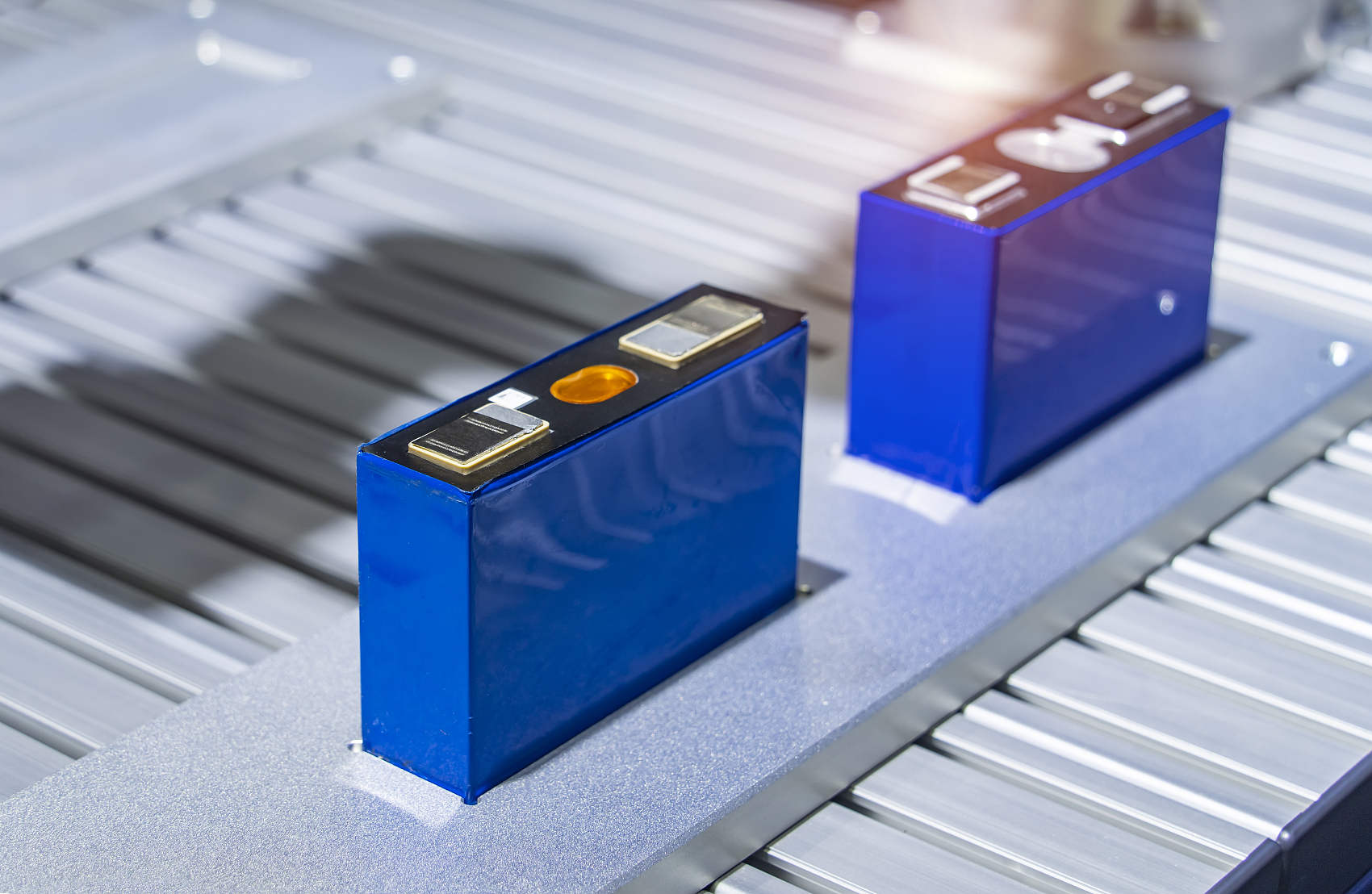
Core Stages of Lithium Battery Manufacturing
Industry references, including the VDMA / PEM RWTH Aachen University “Production Process of a Lithium-Ion Battery Cell” (5th edition, 2026), divide production into three main blocks:
- Electrode manufacturing – converts active materials into coated, densified electrode foils.
- Cell assembly – combines electrodes, separator, and electrolyte into a sealed cell (cylindrical, prismatic, or pouch).
- Cell finishing – electrochemically activates the cell and grades it for performance consistency.
Electrode manufacturing is largely independent of final cell format. Cell assembly varies significantly by format (winding versus stacking). Cell finishing is again largely format-independent.
Electrode Manufacturing
Slurry Mixing
Active cathode materials (commonly LiFePO₄ for industrial cells or NMC for higher-energy designs), conductive additives (carbon black or nanotubes), binder (PVDF or aqueous alternatives), and solvent are mixed under vacuum or controlled atmosphere. Uniform dispersion is critical; agglomerates create local current hotspots and reduce cycle life.
Anode slurry typically uses graphite (or silicon-graphite blends) with binder and solvent. Mixing time, solids content, and viscosity are tightly controlled to ensure subsequent coating uniformity.
Coating and Drying
The slurry is applied to current-collector foil—aluminum for the cathode, copper for the anode—via slot-die, doctor-blade, or transfer coating. Target areal loadings and thickness tolerances are typically held to a few micrometers. Coating quality sets the foundation for capacity consistency across the cell.
Drying removes the solvent in multi-zone ovens. This step is one of the most energy-intensive in conventional (wet) processing and can account for a large share of process energy and floor space. Incomplete drying leaves residual moisture that reacts with electrolyte and degrades performance.
Calendering (Pressing)
Dried electrodes pass through precision rollers that compress the coating to the target density and porosity. Higher density improves volumetric energy density and electronic contact but must not close pores needed for electrolyte wetting or induce particle fracture.
Slitting and Notching
Wide “mother” rolls are slit to the required electrode width. Tabs are formed by mechanical or laser notching. Edge quality and dimensional accuracy prevent internal shorts and ensure reliable tab welding later.
Cell Assembly
Cut electrodes and separator are combined by either winding (cylindrical and some prismatic cells) or stacking / Z-folding (pouch and many prismatic cells). Perfect alignment of anode, separator, and cathode is mandatory; overhang or misalignment creates lithium plating risk or short-circuit paths.
Tabs are welded (ultrasonic, laser, or resistance). The electrode stack or jelly roll is inserted into the housing (metal can or laminated pouch film). Electrolyte is precisely metered under vacuum or controlled atmosphere to ensure complete wetting without excess. Final sealing and, where required, degassing complete the assembly stage.
All assembly steps occur in dry rooms with dew points typically below –40 °C to prevent moisture contamination.
Cell Finishing: Formation, Aging, and Grading
Formation is the first controlled charge–discharge sequence. It creates the solid-electrolyte interphase (SEI) on the anode—a critical passivation layer that enables long cycle life. Formation protocols (current rates, voltage holds, temperature) are chemistry- and design-specific; optimized protocols improve both throughput and subsequent calendar and cycle life.
After formation, cells undergo aging (storage under defined temperature and state-of-charge) to stabilize the SEI and reveal early self-discharge or soft-short defects. Cells are then tested for capacity, internal resistance, open-circuit voltage, and self-discharge rate, then graded into performance bins.
Only cells meeting tight statistical limits proceed to module or pack assembly. High first-pass yield at this stage is a key indicator of upstream process control.
Wet versus Dry Electrode Processes
Conventional wet coating remains dominant, but dry electrode processes have advanced rapidly. Dry methods eliminate solvent mixing and the large drying ovens, reducing energy use, factory footprint, and cost.
| Aspect | Conventional Wet Process | Dry Electrode Process (2026 status) |
|---|---|---|
| Solvent use | Required (NMP or aqueous) | Keiner |
| Drying energy & space | High (major process energy consumer) | Eliminated or minimal |
| Factory footprint | Larger (long oven lines) | Smaller, higher throughput per m² |
| Binder content | Higher (typically 3–5 %+ ) | Lower (down to ~1–2 % in advanced formulations) |
| Scalability (2026) | Mature, high volume | Commercial at scale (e.g., Tesla 4680); pilot-to-production lines expanding (Fraunhofer DRYtraec and others) |
| Energy density potential | Standard | Higher possible via thicker electrodes and lower inactive material |
Tesla reported successful scaled dry-electrode production for both anode and cathode in 4680 cells in early 2026. Parallel European and Asian development programs continue to industrialize continuous dry coating and calendering routes. Adoption remains selective but is accelerating for cost- and sustainability-driven applications.
Quality, Safety, and Standards
Process defects—metallic particles, coating thickness variation, incomplete drying, poor alignment, or improper formation—translate directly into reduced cycle life, elevated internal resistance, or safety incidents. Industrial cells intended for forklifts, heavy machinery, or stationary storage typically target ≥3,500–5,000 cycles at 80 % depth of discharge when manufactured under tight process control with LiFePO₄ chemistry.