
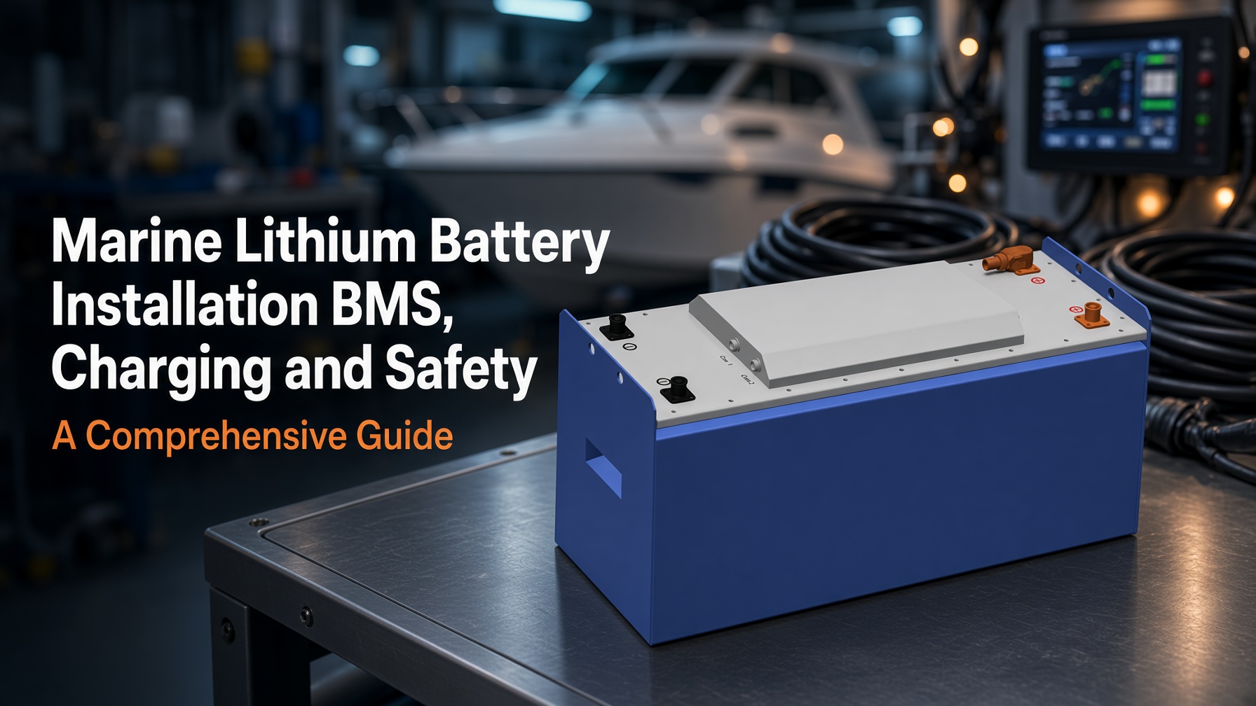
Marine Lithium Battery Installation: BMS, Charging and Safety is no longer a niche retrofit. For small craft and workboats, a correctly designed lithium iron phosphate (LFP) system delivers higher usable energy, faster charging and longer service life than flooded lead-acid. It also introduces failure modes—high fault current, BMS disconnects and thermal events—that lead-acid systems do not exhibit. Success depends on treating the battery, battery management system (BMS), chargers and protection devices as one engineered system rather than a drop-in replacement.
IEEE Spectrum’s 30 May 2026 coverage of platform-matched electrification notes that the battery must be matched to the vessel’s electrical architecture, duty cycle and safety envelope; generic cells or incomplete BMS integration create residual risk that classification societies and insurers will not accept. That principle applies equally to a 5 kWh house bank on a cruising yacht and a multi-hundred-kilowatt-hour propulsion pack on a ferry.
Applicable Standards and Scope
ISO 23625:2025 (Small craft — Lithium-ion batteries) applies to systems greater than 500 Wh used for house loads or propulsion. It requires a BMS that keeps cells inside the manufacturer’s safe operating limits (SOL) and provides cut-off under hazardous conditions, references IEC 62619 and IEC 62620, and mandates operator notification before disconnection of propulsion or other critical systems.
ABYC E-13-2025 (and the 2026 Supplement 65 updates to E-11 and E-13) is the North American reference for recreational vessels. It makes a BMS mandatory on every lithium bank, requires Class T fuses or equivalent high-AIC protection as primary overcurrent protection, and insists on a dedicated manual isolation switch independent of any BMS contactor. Mixing lithium and lead-acid chemistries in series is prohibited.
For commercial and classed vessels the picture is broader: ABS December 2025 Requirements for Use of Lithium-ion Batteries, DNV rules, UK MCA MGN 550 and MGN 681, AMSA guidance referencing AS 3004.2, and emerging KR and IRS rules all converge on the same core requirements—integrated BMS, controlled charging sources, fault-current-rated protection, and documented risk assessment. Installations above roughly 20–30 kWh frequently trigger additional fire-compartment and detection requirements.
Battery Management System Requirements
Marine lithium battery BMS requirements form the primary protective layer. ISO 23625:2025 and ABYC E-13 require the system to:
- Prevent overcharge (high-voltage cut-off), over-discharge (low-voltage cut-off), over-temperature and under-temperature.
- Interrupt overcurrent on both charge and discharge.
- Perform cell balancing (passive or active).
- Provide a visual and/or audible alarm at the normal helm position before disconnecting critical loads or the entire bank.
- Ensure no wiring bypasses the BMS.
Internal BMS units without communication ports or external alarm capability often fail the “notification before disconnect” requirement. Surveyors and the Cruising Association / Inland Waterways Association (CA/IWA) August 2026 guidance therefore favour systems that can coordinate multiple modules, report SOC, SOH, cell voltages and temperatures to a central display, and support at least two access levels so critical settings cannot be altered casually.
For propulsion or essential services, the design must include a residual path—either a small independent lead-acid or LFP buffer for navigation lights, bilge pumps and VHF, or a controlled soft-disconnect sequence that sheds non-essential loads first. ABYC Supplement 65 explicitly recommends this redundancy.
Charging Sources and Integration
Safe lithium battery charging on boats requires every source—engine alternator, shore-power charger, solar MPPT, wind or hydro generator, inverter-charger—to be lithium-compatible and under BMS control. Lithium batteries accept high current for long periods; an unprotected alternator can overheat or suffer load-dump damage if the BMS opens the contactor while the engine is running.
Preferred architectures include:
- External alternator regulation with temperature sensing and current limiting.
- DC-DC chargers between a lead-acid starter battery and the lithium house bank.
- Programmable lithium charge profiles (typically 14.0–14.6 V for a 12 V nominal LFP bank, with short or zero absorption and no float, or a low float if storage mode is required).
- Temperature cut-offs so charging is inhibited below 0 °C or above approximately 45–50 °C.
Opportunity charging in the 15–40 % SOC band and routine operation between roughly 20–30 % and 80–90 % SOC maximises cycle life for LFP cells, which routinely deliver ≥3,500 cycles at 80 % depth of discharge when kept inside these windows. Full 0–100 % cycles and prolonged storage at 100 % SOC accelerate calendar ageing. The CA/IWA guidance and marine practice both emphasise recording the final charger and BMS set-points so later technicians can verify them.
Installation, Protection and Safety
ABYC E-13 lithium installation standards and ISO 23625:2025 address the high short-circuit currents lithium packs can deliver. Overcurrent protection (Class T fuses preferred under current ABYC guidance) must be located as close as practical to the battery positive terminal and sized for both continuous current and the available fault current. If the bank’s prospective short-circuit current exceeds the AIC rating of available devices, the bank must be subdivided.
Preventing thermal runaway in marine lithium systems relies on the combination of BMS temperature monitoring, physical separation or containment, and early detection. Additional installation rules include:
- Secure mechanical mounting that survives marine shock and vibration; reduced mass versus lead-acid must be checked for trim effects.
- Location outside living spaces where possible, protected from engine heat, bilge water, direct sunlight and freezing.
- Appropriate enclosure or ventilation for heat and any cell-vent gases; IP67-rated packs simplify this but do not eliminate the need for overall system design.
- Manual isolation switches that can be operated without relying on the BMS.
- Labelling, torque records, strain relief and chafe protection on all high-current cables.
- Smoke/heat/gas detection linked to the alarm system where the installation warrants it.
- An emergency plan that prioritises isolation and evacuation over attempting to fight a lithium fire.
The August 2026 CA and IWA joint guidance stresses that a professional energy audit, documented system design and insurer notification are prerequisites, not afterthoughts. Unattended charging and “drop-in” claims without supporting data sheets should be treated with caution. ISO 23625:2025 marine battery compliance further requires that systems remain inside manufacturer safe operating limits at all times.
| Aspect | Lead-acid (flooded/AGM) | LFP with full BMS & protection | Incomplete “drop-in” LFP |
|---|---|---|---|
| BMS | None required | Mandatory, no-bypass, alarm before critical disconnect | Often internal only, limited alarms |
| Fault current | Moderate | Very high; Class T or high-AIC required | Frequently under-protected |
| Alternator compatibility | Generally tolerant | Requires regulation / DC-DC / load-dump protection | High risk of damage |
| Cycle life (typical) | 300–1,000 | ≥3,500 at 80 % DoD | Reduced if SOL exceeded |
| Installation complexity | Familiar | Higher; standards-driven | Hidden residual risk |
Installation Sequence
- Perform a detailed energy audit and select capacity, voltage and chemistry (prefer LFP for leisure and most workboat service banks).
- Design the complete electrical architecture: BMS, chargers, alternator protection, fusing, isolation, monitoring and critical-load redundancy.
- Choose a location and mounting that satisfy environmental and structural requirements.
- Install Class T (or equivalent) fuses, manual isolators and correctly rated cabling with documented torque values.
- Commission all charge sources to the manufacturer’s lithium profile and verify BMS set-points and alarms.
- Test disconnect behaviour, alarms and residual critical loads under controlled conditions.
- Produce the handover pack (schematics, settings, data sheets, photos, maintenance schedule) and notify the insurer.
- Establish a routine of opportunity charging, SOC management and periodic connection/SOH checks.
Checklist
- Energy audit completed and capacity chosen for usable energy, not nameplate Ah.
- BMS present, no-bypass, with helm alarm before critical disconnect.
- All charge sources lithium-compatible and temperature-limited.
- Alternator protected against overheating and load dump.
- Class T or high-AIC fuses within 7 in of battery positive; manual isolator independent of BMS.
- Critical loads have residual power path.
- Location dry, ventilated or enclosed, away from living spaces and heat sources.
- Insurer notified and conditions recorded.
- Handover documentation and emergency procedure on board.