


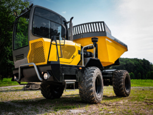
Dumper
We are committed to providing next-generation high-safety lithium-ion battery pack system solutions specifically for dump trucks. We are not just a battery supplier, but a
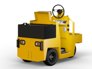
Tow Tractor
At a critical juncture in the global logistics industry’s transformation towards green and efficient operations, tractor units, as the mainstay of transportation, are facing the
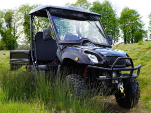
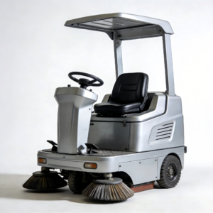
UTV
In every conquest of mountains, deserts, and snowfields, and in every responsibility undertaken in farms, mines, and emergency rescue operations, our lithium battery pack solutions,
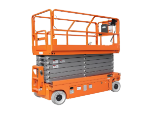
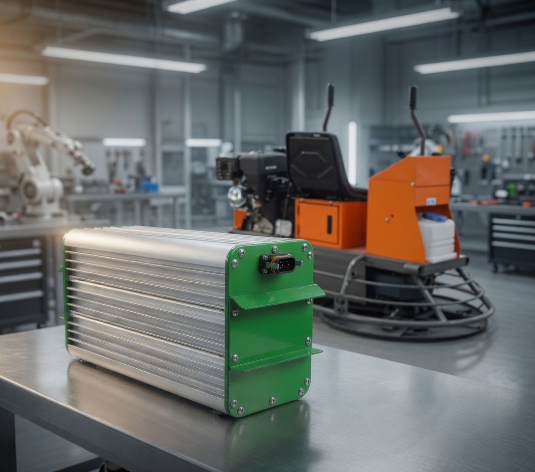
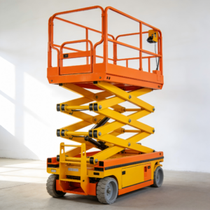
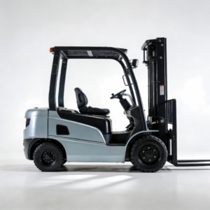
Electric Lift
Our lithium battery pack solutions for electric lifts provide longer-lasting, more reliable, and smarter power in every high-altitude work scenario, including construction sites, equipment installation,

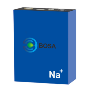
Bosa 24V battery packs for lifting equipments
"Bosa 24V LFP battery packs are a game-changer for our lifting equipment. We’ve been using them for months now, and they perform reliably with consistent power. Highly recommend!"
")
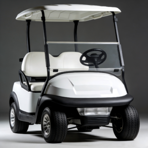
Bosa 48V battery packs for golf carts
"Bosa 48V battery packs for our golf carts have been fantastic. They charge quickly and last a long time. Perfect for long days on the course without worrying about running out of power."
")
Bosa 48V Battery Packs for Forklifts
"We replaced our old forklift batteries with Bosa 48V LFP packs, and the difference is night and day. Faster charging times and better durability, making our warehouse operations much more efficient."
")